
Engineering services
Every wire placed, routed, bundled and buildable.
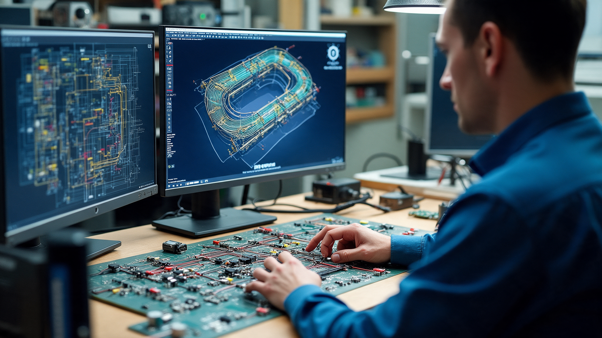
We engineer wiring and harness systems from schematic through 3D routed design to the form board a shop floor builds from — with bundling, segregation, EMC and serviceability decided in the design rather than on the line.
Harness design · 3D routing · Schematics · Bundling · Power distribution · Build support
01 — Why harness work goes wrong late
A harness is the last thing designed and the first thing blamed.
It inherits every other discipline's decisions.
By the time the harness is engineered, the enclosure is fixed, the connectors are chosen, the thermal zones are set and the EMC constraints are inherited. What is left is a routing problem with almost no freedom in it — and a build that has to be achievable by hand.
We do the work where those constraints can still be answered: bundling and segregation rules, routing paths, bend radii, service access and shielding decided against the real 3D geometry, not against a schematic drawn flat.
Then we make it buildable. Flattened harness models and form board designs, installation drawings and instructions, component databases, costing and optimisation — and support during the first builds, when the design meets the people assembling it.
Talk to Zealogics02 — From schematic to shop floor
The same harness, in four representations.
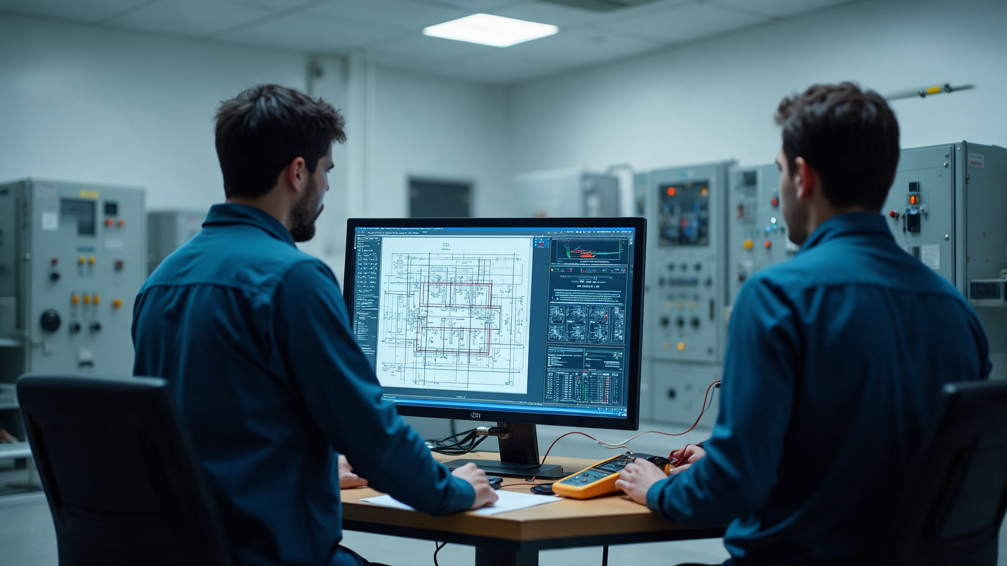
SCHEMATIC · 3D ROUTE · FLATTENED MODEL · FORM BOARD.
03 — What the work covers
Six bodies of work across the harness lifecycle.
Domains we work in
Semiconductor equipment cable and fibre interconnects
Server racks, storage and networking infrastructure
Rail rolling stock and platform wiring
Automotive wiring and electrification
Electronics and hi-tech products
Medical equipment and healthcare devices
Standards engineered against
Schematic and wiring design
Vehicle and equipment schematic design, wiring harness design and the electrical architecture behind them, developed against the functional requirements rather than copied from the previous platform.
3D routed design and conversion
Harness 3D routed design in the real assembly geometry, and 2D to 3D harness conversion for platforms whose wiring only ever existed as a flat drawing.
Bundling, segregation and power distribution
Bundle definition and circuit segregation for signal integrity, EMI/RFI and safety, and power distribution system design across the platform.
Manufacturing representations
Flattened harness models and form board design, harness drawing creation, installation design and instructions — the documents a build cell actually works from.
Component data and costing
Electrical component database creation and maintenance, harness costing and optimisation, and the trade studies that take weight, length and connector count out of a design.
Build support and compliance
Harness product build support through first articles and ramp, with EMC, thermal and standards compliance carried as design constraints rather than checked at the end.
04 — What the shop floor receives
Six outputs that decide whether a harness builds cleanly.
A harness design is only finished when someone who has never seen it can build it correctly the first time.
01
Harness drawings
Complete harness drawings with wire lists, connector tables and terminations unambiguous enough to build from without interpretation.
02
3D routed assembly
Routing carried in the real geometry, with bend radii, clearance, service access and clamp positions resolved.
03
Form board design
Flattened harness model and form board layout dimensioned for the build cell that will lay the harness up.
04
Installation instructions
Installation design and step-by-step instructions covering routing order, fixings and the mistakes that are easy to make.
05
Component database
A maintained electrical component library with the attributes costing, routing and compliance all read from the same source.
06
Cost and optimisation study
Harness costing with the specific changes — routing, gauge, connector choice, bundle split — that reduce it.
05 — How the work runs
Five stages from schematic to first build.
The first article build is part of the engagement, not the point at which it is handed over.
Define
Functional requirements, platform constraints, applicable standards and the electrical architecture.
Schematic
Wiring and schematic design, circuit segregation rules and power distribution.
Route
3D routed design, bundling, clamping, clearance and service access against the real assembly.
Document
Flattened model, form board, harness drawings and installation instructions.
Support the build
Build support through first articles and ramp, with the design changes the floor asks for.
06 — Where it connects
Wiring engineered with the mechanical and electronics design.

ONE GEOMETRY. ONE COMPONENT LIBRARY. ONE TEAM.
07 — Sound familiar?
The conversations that start this work.
“The harness only exists as a flat drawing from 2009.”
2D to 3D conversion
“It builds differently in every cell.”
Form board design
“We are failing EMC and the wiring is the suspect.”
Bundling and segregation
“Harness cost is the biggest line item and nobody has attacked it.”
Costing and optimisation
“Service cannot reach the connector without removing a panel.”
3D routed design
“Our component data lives in four spreadsheets.”
Component database
08 — The rest of the practice
Five more engineering disciplines.
Programmes rarely stay inside one discipline. A tool that needs embedded firmware usually needs the mechanics, the harness and the line that builds it too.
Embed
Embedded Systems
Turn a product concept into hardware and the firmware that runs it — schematics, layout, bring-up, certification and the years of sustenance after.
Explore
Connect
Factory Automation
Equipment software, SECS/GEM and GEM300 integration, EAP and MES connectivity, manufacturing data — and the intelligence layer built on top of them.
Explore
Design
Silicon Engineering
Full-chip design across ASICs, SoCs, FPGAs and chiplets — architecture, RTL, verification, DFT, analog and physical design through tape-out and post-silicon validation.
Explore
Design
Mechanical Engineering
Product design and development, engineering analysis and simulation, model-based systems engineering, and the change management that keeps a design alive for a decade.
Explore
Build
Manufacturing
PCB, turnkey, box build, harness and cleanroom assembly under the same engineering ownership as the design — with the test capability to prove what shipped.
Explore
Have a problem worth solving?
Send us the schematic — or the harness that will not build.
A review of the routing, the form board or the build instructions usually makes it obvious whether the problem is the design, the documentation or the process.